Computer Networking
- tags
- Operating Systems
Introduction
What is the Internet?
The internet is a computer network that interconnects hundreds of millions of computing devices throughout the world.
End systems are connected together by a network of communication links and packet switches. The common packet switches are routers and link-layer switches. The sequence of communication links and packet switches traversed by a packet from the sending end system to the receiving end system is known as the route, or path through a network.
End systems access the internet through Internet Service Providers (ISPs). ISPs provide a variety of types of network access to the end systems.
End systems, packet switches and other pieces of the Internet run protocols that control the sending and receiving of information within the internet. The Internet’s principal protocols are the Transmission Control Protocol (TCP) and the Internet Protocol (IP), known collectively as TCP/IP.
What is a protocol?
A protocol defines the format and the order of messages exchanged between two or more communicating entities, as well as the actions taken on the transmission and/or receipt of a message or other event.
The Network Edge
The computers and other devices that are connected to the Internet are often called end systems. This is because they sit at the edge of the Internet. Each system are also referred to as hosts because they host application programs such as the web browser, or a server. Hosts are sometimes further divided into 2 categories: clients and servers.
Access networks include the digital subscriber line (DSL), cable, and fiber to the home (FTTH). Ethernet and WiFi access networks are now common across enterprise, university campuses as well as in homes. Wide-area wireless access such as 4G and LTE provide wireless access to the Internet by sending and receiving packets through a base station.
Physical Mediums
For reach transmitter-receiver pair, bits are interchanged. These bits are sent by electromagnetic waves, or optical pulses across a physical medium.
The least expensive and most commonly used transmission medium is the twisted-pair copper wire. It consists of 2 insulated copper wires, twisted togethter to reduce electrical interference from similar pairs close by.
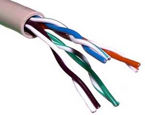
Figure 1: A Unshielded-Twisted-Pair (UTP) cable
Coaxial cables consist of 2 copper conductors, but the two conductors are concentric rather than parallel. These achieve high data transmission rates, and can be used as a guided shared medium. They are common in cable television systems.
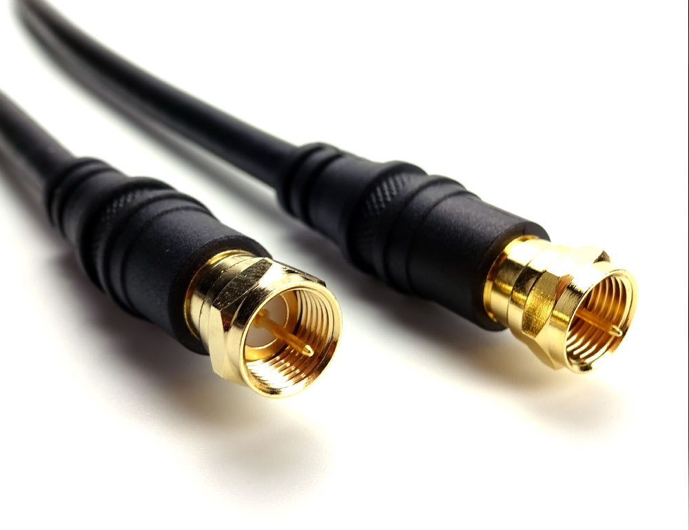
Figure 2: A Coaxial cable
The Network Core
Packet Switching
In a network application, end systems exchange messages with each other. Messages can contain anything the application designer wants. To send a message from a source end system to a destination end system, the source breaks long messages into smaller chunks of data known as packets. Each packet travels through communication links and packet switches. Packets are transmitted over each communication link at a rate equal to the full transmission rate of the link. So if a source end system or a packet switch is sending a packet of \(L\) bits over a link with transmission rate \(R\) bits/sec, then the time to transmit the packet is \(\frac{L}{R}\) seconds.
Most packet switches use store-and-forward transmission at the inputs to the links. This means that the packet switch must receive the entire packet before it can begin to transmit the first bit of the packet onto the outbound link.
Each packet switch has multiple links attached to it. For each attached link, the packet switch has an output buffer, which stores packets that the router is about to send into that link. If an arriving packet needs to be transmitted onto a link but finds the link busy with the transmission of another packet, the arriving packet must wait in the output buffer. This results in output buffer queuing delays. Packet loss will occur – either the arriving packet or one of the already-queued packets will be dropped.
How does a router determine which link it should forward the packet onto? In the Internet, each end system is assigned an IP address. The source end system includes the destination IP address in the packet’s header. Each router has a forwarding table that maps destination addresses to its outbound links.
Circuit Switching
In circuit-switched networks, the resources needed along apath (buffers, link transmission rate) to provide for communication between end-systems are reserved for the duration of the communication session between the end systems. Traditional telephone networks are examples of such circuit-switched networks.
A circuit in a link is implemented with either frequency-division multiplexing (FDM) or time-division multiplexing (TDM). With FDM, the frequency spectrum of a link is divided up among the connections established across the link. For a TDM link, time is divided into frames of fixed duration, and each frame is divided into a fixed number of time slots.
Packet switching is offers better sharing of transmission capacity than circuit switching, and is simpler and more efficient. However, circuit switching can be more suitable for real-time services.
A Network of Networks
A PoP is a group of one or more routers in the provider’s network where customer ISPs can connect into a provider ISP. For a customer network to connect to a provider’s PoP, it can lease a high-speed link from a third-party telecommunications provider to directly connect one of its routers to a router at the PoP. Any ISP may choose to multi-home, that is, to connect to two or more provider ISPs.
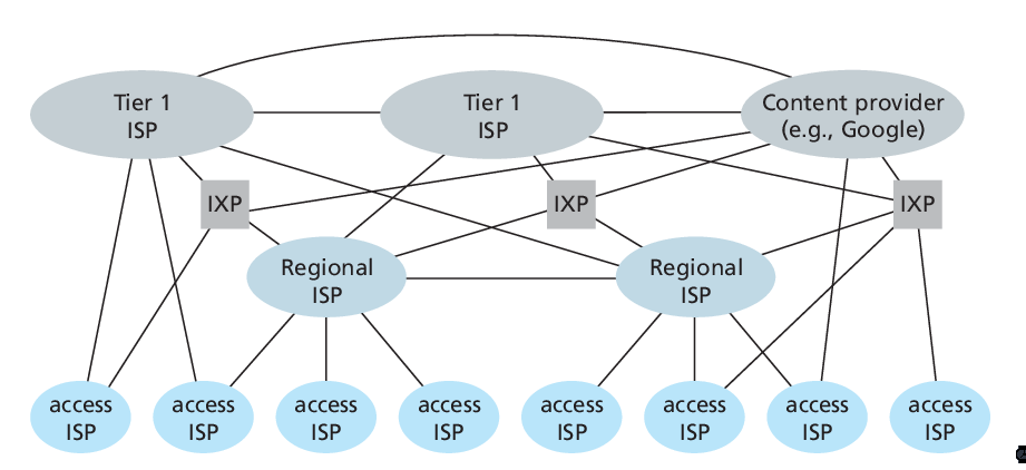
Figure 3: Interconnection of ISPs
Delays in Packet-Switched Networks
- Processing delay
- Time needed to check bit-level errors in packet
- Queuing delay
- Time spent waiting to be transmitted in the link
- Transmission delay
- Equal to \(L/R\). Transmission delays are typically on the order of microseconds to milliseconds in practice.
- Propagation delay
- The bit propagates at the propagation speed of the link, depending on the physical medium. This speed is roughly the speed of light.
Packet loss can occur when it arrives to find a full queue. The router will drop the packet.
Given these delays, we can compute the end-to-end delay.
\begin{equation} d_{\text{e2e}} = N(d_{\text{proc}} + d_{\text{trans}} + d_{\text{prop}}) \end{equation}
This does not account for the average queuing delay of the node.
Throughput
The instantaneous throughput at any instant of time is the rate (in bits/sec) at which a host is receiving the file.
Protocol Layers and Their Service Models
The Internet Protocol stack consists of 5 layers: the physical link, network, transport, and application layers. The OSI reference model consists of 7 layers.
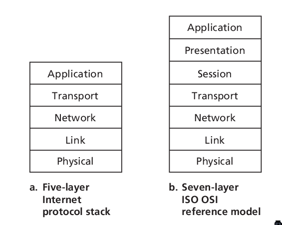
Figure 4: IP stack and ISO OSI reference model
- Application layer
- network applications and application layer protocols reside here. These protocol include HTTP, SMUT and FTP. The packet of information at this layer is a message.
- Transport Layer
- in the Internet there are 2 transport protocols: TCP and UDP, each with their own use-case. Each transport-layer packet is called a segment.
- Network Layer
- responsible for moving packets known as datagrams from one host to another. It has many routing protocols.
- Link Layer
- The network layer relies on this layer to deliver the datagram to the next node along the route. These services depend on the specific link-layer protocol employed for the link. For example, cable access networks may use the DOCSIS protocol. Link layer protocols include Ethernet and WiFi. Link-layer packets are referred to as frames.
- Physical Layer
- responsible of moving individual bits across physical mediums.
Application Layer
Networking applications have application-layer protocols that define the format and order of the messages exchanged between processes, as well as define the actions taken on the transmission or receipt of a message.
Example of application-layer protocols include:
- HTTP (HyperText Transfer Protocol [RFC 2616]), which defines how messages are passed between browser and web-server
- SMTP (Simple mail Transfer Protocol [RFC 821]), a protocol for mail exchange
Client and Servers
A network application protocol typically has 2 parts, a client side and a server side. The host that initiates the session is often labeled the client. A host can act as both a client and server at the same time. As a concrete example, a mail server host runs the client side of SMTP (for sending email), and the server side of SMTP (for receiving email).
Sockets
Applications communicate by sending messages over a socket. A process’s socket can be thought of as the process’s door: it sends messages into, and receives messages from the network through this socket. It is the interface between the application layer and transport layer within a host.
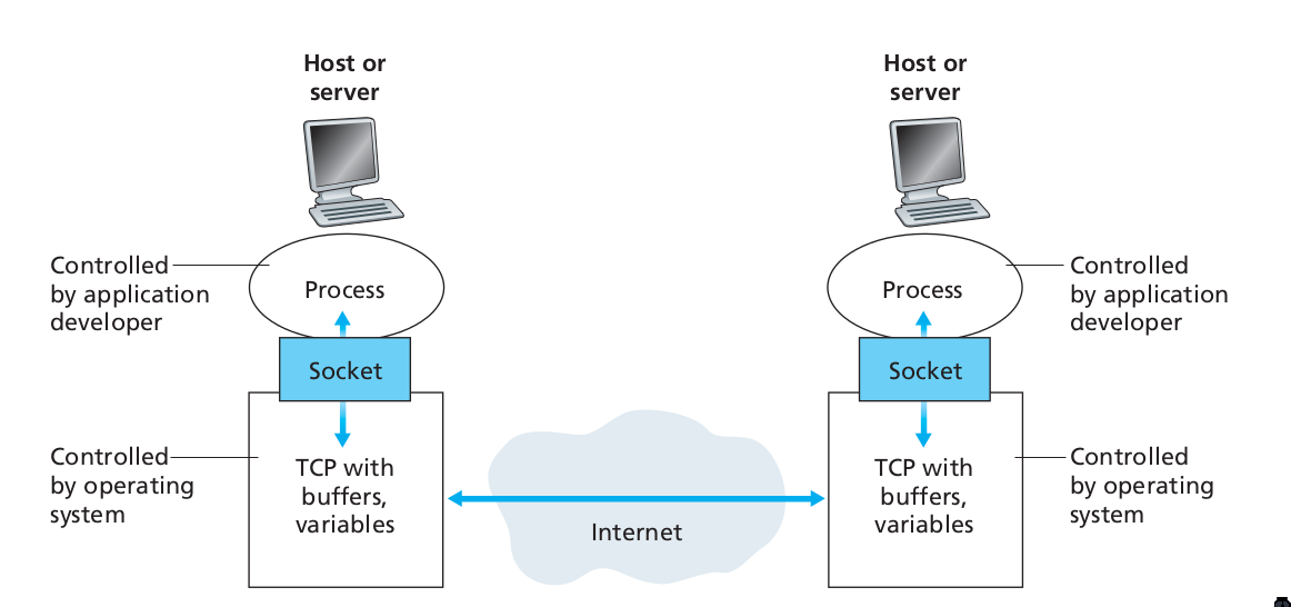
Figure 5: Application processes, sockets, and underlying transport protocol
Addressing Processes
In order for a process on one host to send a message to a process on another host, the sending process must identify the receiving process. To identify the receiving process, one must specify these 2 pieces of information:
- The name or address of the host machine
- An identifier that specifies the identity of the receiving process on the destination host
In Internet applications, the destination host is specified by its IP address. The IP address is a 32-bit quantity that uniquely identifies the interface that connects to the internet. These need to be globally unique. A receive-side port number serves the purpose of identifying the correct process on the system.
The user agent is an interface between the user and the network application. For example, user agents for browsing the Web include Firefox and Chrome.
Transmission Control Protocol (TCP)
The Internet makes available 2 transport protocols to applications, namely UDP and TCP. When a developer creates a new application for the Internet, they must choose between the two protocols. Each protocol offers a different service model.
TCP includes a connection-oriented service and a reliable data transfer service.
TCP has the client and server exchange transport-layer control information with each other before the application-level messages begin to flow. This hand-shaking procedure alerts the client and server, and a TCP connection is said to exist between the sockets of the 2 processes. When the application is done with sending messages, it must tear down the connection.
The communicating processes can rely on TCP to deliver all data sent without error, and in proper order. TCP also includes a congestion-control mechanism. The mechanism throttles a process when the network is congested, attempting to limit each TCP connection to its fair share of network bandwidth. This control mechanism benefits the Internet, rather than the direct benefit of the communicating processes.
TCP does not provide:
- A guaranteed minimum transmission rate
- Any delay guarantees
User Datagram Protocol (UDP)
UDP is connectionless, so there is no handshaking before the 2 processes start to communicate. It provides an unreliable data transfer service. Hence, it provides no guarantee that a message will ever reach the receiving socket. Messages that do arrive may arrive out-of-order.
On the other hand, UDP does not include a congestion-control mechanism, so a sending process can pump data into a UDP socket at any rate.
This protocol is largely used by real-time applications.
HTTP
HTTP is implemented in 2 programs: a client program and a server program. Clients and servers talk to each other by exchanging HTTP messages. HTTP defines the structure of these messages.
HTTP use TCP as their underlying transport protocol. The HTTP client first initiates a TCP connection with the server. Once the connection is established, the browser and server processes access TCP through their socket interfaces. The client sends HTTP request messages through the socket interface, and receives HTTP response messages from its socket interface.
HTTP can use both nonpersistent and persistent connections. The use of persistent connections is the default mode for HTTP/1.1.
With non-persistent connections, each TCP connection is closed after the server sends the object. T he response time for a new HTTP request is 2 round-trip times plus the transmission time at the server of the HTML file.
With persistent connections, the server leaves the TCP connection open after sending a response. Subsequent requests and responses between the same client and server can be sent over the same connection.
Here’s an exmple of the HTTP Request message:
  GET /somedir/page.html HTTP/1.1
  Host: www.someschool.edu
  Connection: close
  User-agent: Mozilla/4.0
  Accept-language: fr
  (extra carriage return, line feed)
The general form of a request message looks like this:
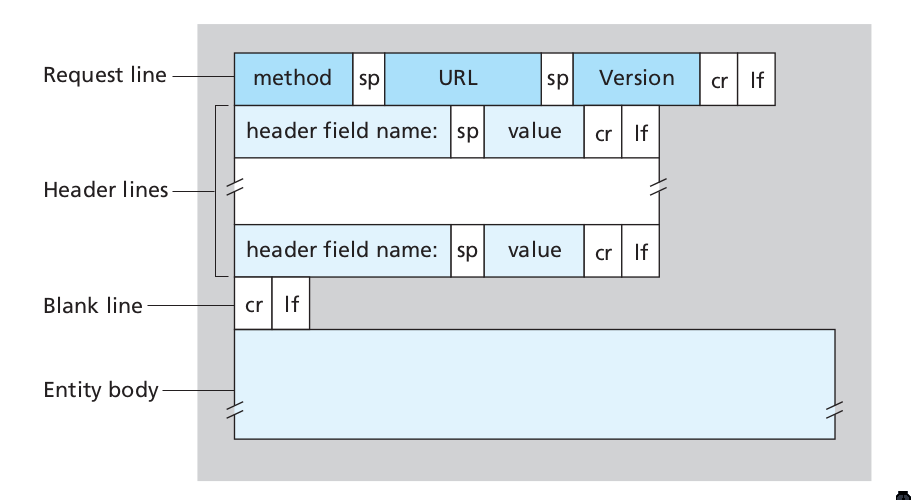
Figure 6: Format of a HTTP request message
The response message looks like this:
  HTTP/1.1 200 OK
  Connection: close
  Date: Thu, 06 Aug 1998 12:00:15 GMT
  Server: Apache/1.3.0 (Unix)
  Last-Modified: Mon, 22 Jun 1998 09:23:24 GMT
  Content-Length: 6821
  Content-Type: text/html

  (data data ...)
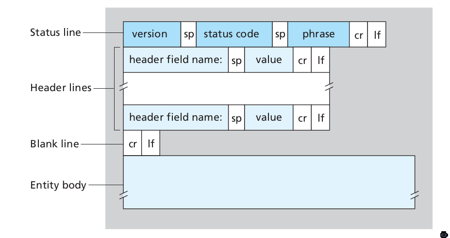
Figure 7: Format of a HTTP response message
User-server Interaction: Cookies
The HTTP server is stateless. This simplifies server design, and permits engineers to develop high-performance web servers that can handle thousands of simultaneous TCP connections. For a website to identify users, HTTP uses cookies. Cookies, defined in [RFC 6265], allows sites to keep track of users.
Cookie consists of 4 components:
- A cookie header line in the HTTP response message
- A cookie header line in the HTTP request message
- A cookie file kept on the user’s end system, and is managed by the user’s web browser
- A back-end database at the Web site
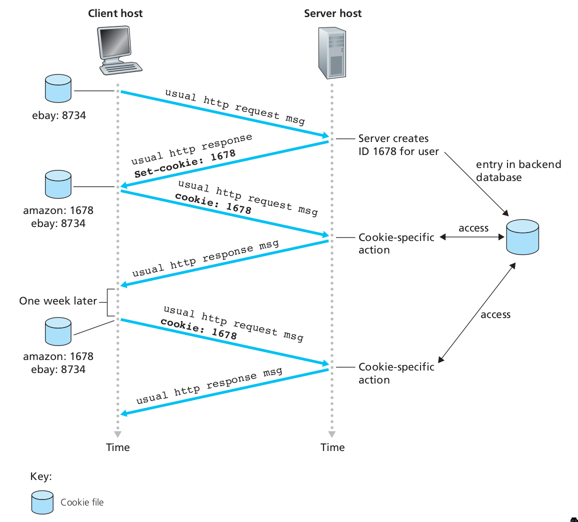
Figure 8: Keeping user state with cookies
Web Caching
A web cache – also called a proxy server – may satisfy HTTP requests on behalf of an origin Web server.
DNS
People prefer the more mnemonic hostname identifier (e.g.
www.google.com), whil emrouters prefer fixed-length, hierarchically
structured IP addresses.
In order to reconcile these different preferences, we need a directory service that translates hostnames to IP addresses. This is the main task of the Internet’s Domain Name System (DNS).
The DNS is (1) a distributed database implemented in a hierarchy of name servers and (2) an application-layer protocol that allows hosts and name servers to communicate in order to provide the translation service. The DNS protocol runs over UDP and uses port 53.
DNS is commonly employed by other application-layer protocols, such as HTTP, to translate user-supplied host names to IP addresses.
No one name server has all of the mappings of all of the hosts in the internet. DNS uses a large number of name servers organized in a hierarchical fashion and distributed around the world.
- Local name servers
- Each ISP – such as a university – has a local name server. when a host issues a DNS query message, the message is first sent to the host’s local name server.
- Root name servers
- There are a dozen or so root name servers, situated primarily in North America. When a local name server is unable to respond to a DNS query, it acts as a DNS client and makes a DNS query to a root name server.
- Authoritative name servers
- The root name server may not know the IP address of a particular host. Instead the root name server knows the IP address of the authoritative name server that has the desired mapping. A name server is authoritative for a host if it always has a DNS record that translates the host’s hostname to that host’s IP address. When an authoritative name server is queried by a root server, the authoritative name server responds with a reply containing the desired mapping.
<biblio.bib>
Transport Layer
The transport layer resides between the application and network layers. A transport layer protocol provides for logical communication between application processes running on different hosts. Although the communicating processes are not physically connected to each other, from the application’s viewpoint, they are physically connected. Application processes use the logical communication provided by the transport layer to send messages to each other, free from the worries of the physical infrastructure used to carry these messages.
Transport-layer protocols are implemented on end-systems but not in network routers. Network routers only act on the network-layer fields of the layer 3 PDUs.
On the sending side, the transport layer converts the messages it receives from a sending application process into 4-PDUs (transport-layer protocol data units). This is done by (possibly) breaking the application messages into smaller chunks and adding a transport-layer header to each chunk. The transport layer then passes these 4-PDUs to the network layer, which are then translated into 3-PDUs.
On the receiving side, the transport layer removes the transport header from the 4-PDUs, reassembles the message, and passes it to the receiving application process.
All transport-layer protocols provide an application multiplexing/demultiplexing service. A transport protocol can possibly provide other services to invoking applications, including reliable data transfer, bandwidth guarantees and delay guarantees.
Relationship between the transport layer and network layer
The transport layer lies just above the network layer. The transport-layer protocol provides logical communication between processes running on different hosts, while the network-layer protocol provides logical communication between hosts.
The transport-layer protocols live in the ned-systems. Within an end-system, a transport protocol moves messages from application processes to the network edge and vice versa, but it doesn’t have any say about how the messages are moved within the network core. A computer network may make available multiple transport protocols, with each protocol offering a different service model to applications.
The services that a transport protocol can provide are often constrained by the service model of the underlying network-layer protocol. For example, if the network-layer protocol cannot provide bandwidth or delay guarantees, then the transport-layer protocol on top of it cannot as well.
Overview of Transport layer in the Internet
the Internet, and more generally a TCP/IP network, makes available two distinct transport-layer protocols to the application layer: UDP (User Datagram Protocol) and TCP (Transmission Control Protocol).
UDP provides an unreliable, connectionless service to the invoking application. TCP provides a reliable, connection-oriented service to the invoking application.
The Internet’s network-layer protocol is called IP, which stands for Internet Protocol. The IP service model is a best-effort delivery service. This means that IP makes its “best effort” to deliver segments between communicating hosts, but makes no guarantees.
The fundamental responsibility of TCP and UDP is to extend IP’s delivery service between 2 end systems to a delivery service between two processes running on the end system. Extending host-to-host delivery to process-to-process delivery is called application multiplexing and demultiplexing. UDP and TCP also provide error-detection fields in their headers. These are the only 2 services UDP provides.
TCP offers additional services. First, it provides reliable data transfer. Using flow control, sequence numbering, acknowledgments, and timers, TCP ensures that data is delivered correctly and in order. TCP also uses congestion control, which is a service provided to the Internet as a whole rather than a service provided to the invoking application. This is done by regulating the rate at which the sending-side TCPs can send traffic into the network.
Multiplexing and Demultiplexing Applications
The job of delivering the data in a transport-layer segment to the correct application process is called demultiplexing. The job of gathering data at the source host from different application processes, enveloping the data with header information to create segments and passing to the network layer, is called multiplexing.
This is performed by TCP and UDP by including two special fields in the segment headers: the source port-number field and the destination port-number field.
The port numbers ranging from 0 to 1023 are called well-known port numbers, and are restricted, which means that they are reserved for use by well-known application protocols such as HTTP and FTP: HTTP uses port 80, and FTP uses port 21.
To identify the appropriate host, the transport segment also contains the source and destination IP addresses.
Connectionless Transport: UDP
UDP, defined in RFC 768, does as little as a transport protocol can do. Aside from multiplexing/demultiplexing and some light error checking, it adds nothing to IP.
UDP takes messages from the application processes, attaches source and destination port fields for the multiplexing/demultiplexing service, adds two other small fields, and passes the resulting segment to the network layer. The network layer encapsulates the segment into an IP datagram and then makes a best-effort attempt to deliver the segment’s data to the correct application process.
Note that with UDP there is no handshaking between sending and receiving transport-layer entities before sending a segment. Hence, UDP is said to be connectionless.
DNS is an example of an application-layer protocol that uses UDP.
There are many applications more suited to UDP for the following reasons:
- No connection establishment
- TCP uses a three-way handshake before it starts to transfer data. UDP does not introduce any delay to establish a connection.
- No connection state
- TCP maintains connection state in the end systems. This connection state includes receive and send buffers, congestion control parameters, and sequence and acknowledgment number parameters. Hence, a server devoted to a particular application can typically support many more active clients over UDP.
- Small packet header overhead
- The TCP segment has 20 bytes of header overhead per segment, while UDP only has 8 bytes of overhead.
- Unregulated send rate
- TCP has a congestion control mechanism that throttles the sender when one or more links between sender and receiver become excessively congested. This throttling can have severe impact on real-time applications. The speed at which UDP sends data is only constrained by the rate at which the application generates data, the capabilities of the source, and the access bandwidth to the Internet.
TCP cannot be employed with mulitcast, multicast applications run over UDP. It is possible to have reliable data transfer using UDP, by building this into the application itself.
UDP Segment Structure
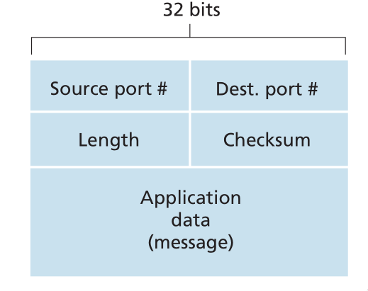
Figure 9: UDP segment structure
The UDP segment structure is defined in RFC 768. The UDP header has only four fields, each consisting of 2 bytes. The port numbers allow the destination host to pass the application data to the correct process running on the destination end system. The length field specifies the number of bytes in the UDP segment (header plus data). An explicit length value is needed since the size of the data field may differ between UDP segments.
The checksum provides for error detection. It determines whether bits within the UDP segment have been altered as it moved from source to destination. UDP at the sender side performs the 1s complement of the sum of all the 16-bit words in the segment, with any overflow encountered during the sum being wrapped around. This result is put in the checksum field of the UDP segment.
For example, suppose we have 3 16-bit words:
0110011001100000
0101010101010101
1000111100001100
The sum of the first two words is:
0110011001100000
0101010101010101
----------------
1011101110110101
Adding the third word gives:
1011101110110101
1000111100001100
----------------
0100101011000010
Note this last addition had overflow, which is wrapped around. Thus the 1s complement of the sum 0100101011000010 is 1011010100111101.
UDP provides a checksum because there is no guarantee that all the links between source and destination provide error checking. One of the links may use a link-layer protocol that does not provide error checking. Even if segments are correctly transferred across a link, it’s possible that bit errors could be introduced when a segment is stored in a router’s memory. Hence, UDP must provide error-detection at the transport layer, on an end-end basis. Because IP is supposed to run over just about any layer-2 protocol, it is useful for the transport layer to provide error checking as a safety measure. UDP provides nothing for error recovery. Some implementations of UDP simply discard the damaged segment; others pass the damaged segment to the application with a warning.
Principles of Reliable Data Transfer
The service abstraction provided to the upper-layer entities is that of a reliable channel through which data can be transferred. With a reliable channel, no transferred data bits are corrupted or lost, and all are delivered in the order in which they are sent. This is the service model that TCP offers to the Internet applications that invoke it.
It is the responsibility of a reliable data transfer protocol to implement this service abstraction. This task is made more difficult by the fact that the layers beneath it may be unreliable. Here, we develop increasingly complex models for the sender and receiver sides of a reliable data transfer protocol.
Network Layer
The network layer implements host-to-host communication service. Unlike the transport and application layer, there is a piece of the network layer in each and every host and router in the network.
Forwarding and Routing
- Forwarding
- Forwarding involves the transfer of a packet from an incoming link to an outgoing link within a single router.
- Routing
- Routing involves all of a routers, whose collective interactions via routing protocols determine the paths that packets take on their trips from source to destination.
Every router has a forwarding table. A router forwards a packet by examining the value of a field in the arriving packet’s header. and then using this header value to index into the router’s forwarding table.
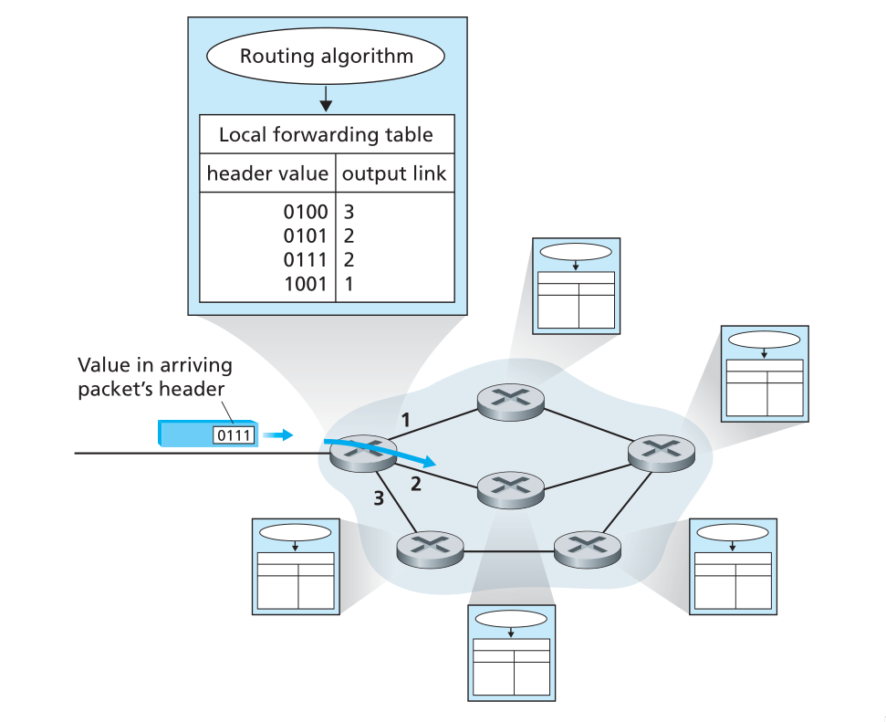
Figure 10: Routing algorithm determines value in forwarding table
Link-layer switches base their forwarding decision on values in the fields of the link layer frame; switches are thus referred to as link-layer devices. Routers base their forwarding decision on the value in the network layer field, and are thus network-layer devices. Routers require services at both layer 2 and 3.
routers along the chosen path from source to destination require handshaking with each other in order to set up state before network-layer data packets within a given source-to-destination can begin to flow. This process is referred to as connection setup.
Services network protocols may provide
There are many potential services a network protocol may provide, and these include:
- guaranteed delivery
- guaranteed delivery with bounded delay
- in-order packet delivery
- guaranteed minimal bandwidth
- guaranteed maximum jitter
- security services
The Internet’s network layer protocol provides a single service, known as the best-effort service.
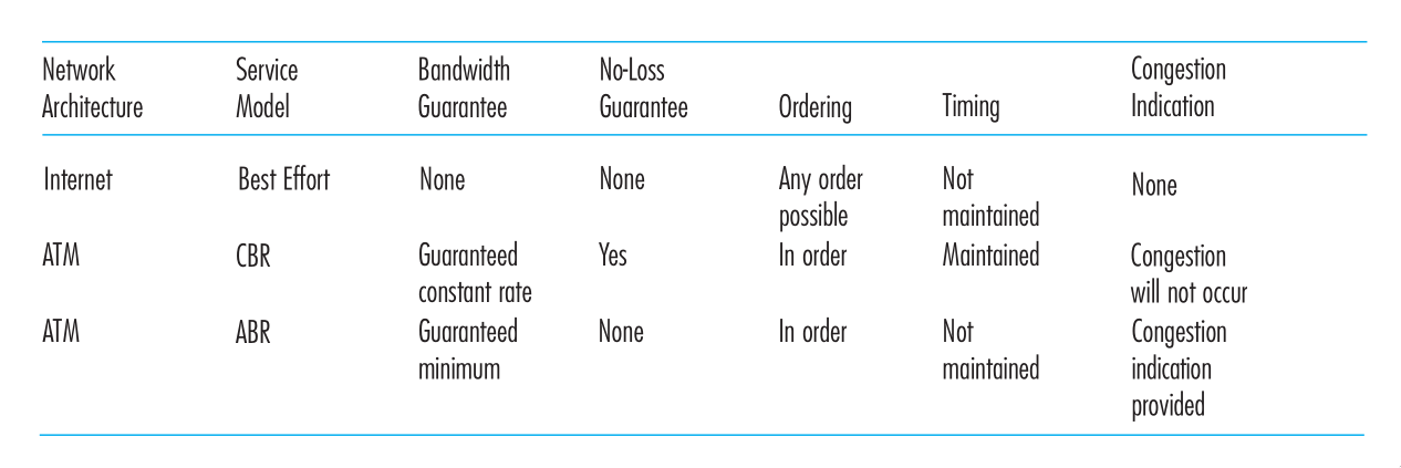
Figure 11: Internet, ATM CBR and ATM ABR Service Models
It may seem like the Internet network-layer protocol provides no service at all. ATM networks provide service models with more services than the Internet IP protocol.
Virtual Circuit and Datagram Networks
Computer networks that provide only a connection service at the network layer are called virtual-circuit networks. Computer networks that provide only a connectionless service an the network layer are called datagram networks.
The implementations of connection-oriented services in the transport layer and connection service in the network layer are fundamentally different: the network-layer connection service is implemented in the routers in the network core, as well as in the end systems.
VC networks
A VC consists of:
- a path between the source and destination hosts
- VC numbers, one number for each link along the path
- entries in the forwarding table in each router along the path
A packet belonging to a virtual circuit will carry a VC number in its header. Because a virtual circuit may have a different VC number on each link, each intervening router must replace the VC number of each traversing packet with a new VC number. This VC number is obtained from the forwarding table.
In a VC network, the network’s routers must maintain connection staet information for the ongoing connections. Specifically, each time a new connection is established across a router, a new connection entry must be added to the router’s forwarding table, and each time a connection is released, an entry must be removed from the table.
There are 3 phases in a virtual circuit:
- VC Setup: The sending transport layer contacts teh network layer, specifies the receiver address and waits for the network to set up the VC. The network layer determines the path between sender and receiver, that is, the series of links and routers through which all packets of the VC will travel. The network layer also determines the VC number for each link along the path. Finally, the network layer adds an entry in the forwarding table in each router along the path. The network layer may also reserve resources (e.g. bandwidth) along the path of the VC during the setup.
- Data transfer: the packet can begin to flow along the VC
- VC Teardown: The sender (or receiver) informs the VC of its desire to terminate the VC. The network layer typically informs the end system on the other side of the network, and update the forwarding tables in each of the packet routers on the path from source to destination that the VC no longer exists.
The messages that are passed between routers to set up the VC are known as signalling messages, and the protocols to exchange these messages are referred to as signaling protocols.
Datagram Networks
In a datagram network, each time an end system wants to send a packet, it stamps the packet with the address of the destination end system and then pops the packet into the network. There is no VC setup, and routers do not maintain any state information.
As a packet is transmitted from source to destination, it passes through a series of routers. Each of these routers use the packet’s destination address to forward the packet.
Routers typically use the longest prefix matching rule, which matches the packet’s IP address to a prefix entry in the forwarding table to choose the link interface to forward the packet.
The Internet Protocol (IP)
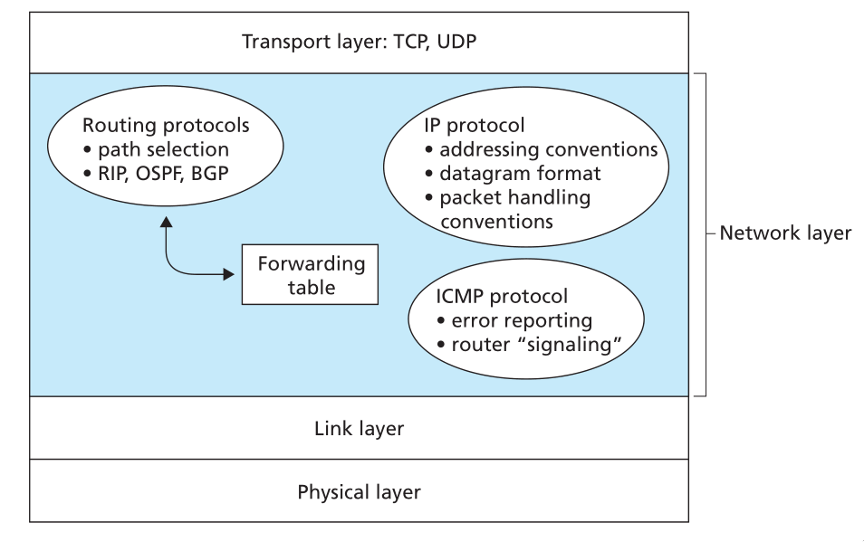
Figure 12: Illustration of the Internet’s network layer
Datagram
The network-layer packet is referred to as a datagram. The format of a datagram is as follows:
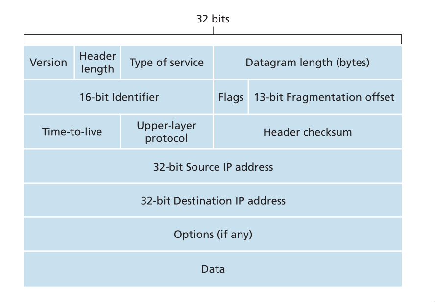
Figure 13: IPv4 datagram format
The key fields include:
- Version number
- the IP protocol version of the datagram
- Header length
- An IPv4 datgram may have variable header length, but most IP datagrams do not contain options.
- Type of service
- the specific level of service to be provided is a policy issue determined by the router’s administrator. Services include high throughput, and low delay.
- Datagram length
- the total length of the IP datagram (header plus data), measured in bytes
- Identifier flags, framentation offset
- these concern IP fragmentation. IPv6 disallows fragmentation in the routers.
- TTL
- the time to live field ensure that datagrams do not circulate forever in the network.
- Protocol
- This fieldl is used only when an IP datagram reaches its final destination. The value indicates the specific transport-layer protocol (e.g. TCP) to which the data portion of the IP datagram should be passed.
- Header checksum
- Aids a router in detecting bit errors in a received IP datagram. Routers typically discard erroneous datagrams.
- Source and destination IP addresses
- When a source creates a datagram, it inserts its IP address into the source IP address, and inserts the address of the destination into the destination IP address
- Options
- These allow extensions to the IP header.
- Data
- The payload to transfer
IP Datagram Fragmentation
Not all link-layer protocols can carry network-layer packets of the same size. For example, Ethernet frames can carry up to 1500 bytes of data, whereas frames for some wide-area links can carry no more than 576 bytes. The maximum amount of data that a link-layer frame can carry is called the maximum transmission unit (MTU). Because each IP datagram is encapsulated within the link-layer frame for transport from one router to the next, the MTU of the link-layer protocol places a hard limit on the length of an IP datagram.
To resolve this issue, an IP datagram needs to be able to split itself into two or more smaller IP datagrams. These smaller datagrams are called fragments. Fragments need to be reassembled before reaching the transport layer at the destination.
To perform the reassembly task, IPv4 put identification, flag and fragmentation offset fields in the datgram header.
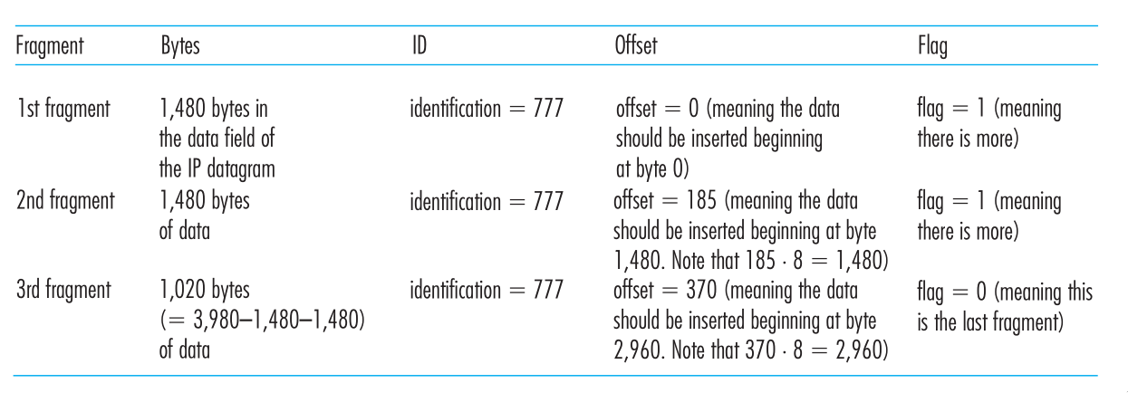
Figure 14: IP fragments
IPv4 addressing
A host typically only has 1 link into the network. A router has multiple interfaces, one for each of its links. IP requires each host and router interface to have its own IP address. Thus, an IP address is technically associated with an interface, rather than with the host or router containing that interface.
Each IP address is 32 bits long, thus there are a total of \(2^32\) possible IP addresses. These addresses are typically written in dotted-decimal notation (e.g. 193.32.216.9).
A subnet is also called an IP network, and refers to the network interconnecting several interfaces via one router interface. IP addressing assigns an address to this subnet: 223.1.1.0/24, where the /24 notation, sometimes known as the subnet mask, indicates that the leftmost 24-bits of the 32-bit quantity define the subnet address.
To determine the subnets in the system:
- detach each interface from its host or router, creating islands of isolated networks, with interfaces terminating the endpoints of the isolated networks.
- each of these isolated networks is a subnet.
The Internet’s address alignment strategy is known as Classless Interdomain Routing (CIDR). An organization is typically assigned a block of contiguous addresses, that is, a range of addresses with a common prefix.
Obtaining a block of addresses
The ISP itself may be allocated a block of IP addresses, for example 200.23.16.0/20. The ISP can in turn divide its address block into equal-sized contiguous address blocks, and give these blocks to organizations. Internet Corporation for Assigned Names and Numbers (ICANN) is the global authority on managing IP addresses, and is also responsible for the DNS root servers.
Obtaining a host address: The dynamic host configuration protocol
Once an organization has obtained a block of addresses, it can assign individual IP addresses to the host and router interfaces in its organization. Host addresses can be configured via the Dynamic Host Configuration Protocol (DHCP). It allows a host to obtain (be allocated) an IP address automatically. A host may be assigned a temporary IP address that will be different each time the host connects to the network.
For a newly arriving host, the DHCP protocol is a 4-step process:
- DHCP server discovery: A DHCP discover message is sent using a UDP packet to port 67. The DHCP client creates an IP datagram containing its DHCP discover message along with the broadcast IP address of 255.255.255.255, and a “this host” source IP address of 0.0.0.0. The DHCP client passes the IP datagram to the link layer, which broadcasts this rame to all nodes attached to the subnet.
- DHCP server offer(s): A DHCP offer message is broadcast to all nodes on the subnet, using the IP broadcast address of 255.255.255.255. The client may be able to choose from among several offers, if there are several DHCP servers present on the subnet. The DHCP offer message contains the transaction ID of the received discover message, the proposed IP address, and an IP address lease time.
- DHCP request: the client will choose among the DHCP offers, and respond to the selected offer with a DHCP request message, echoing back its configuration parameters
- DHCP ACK: The server responds to the DHCP request message with a HCP ACK message, confirming the requested parameters.
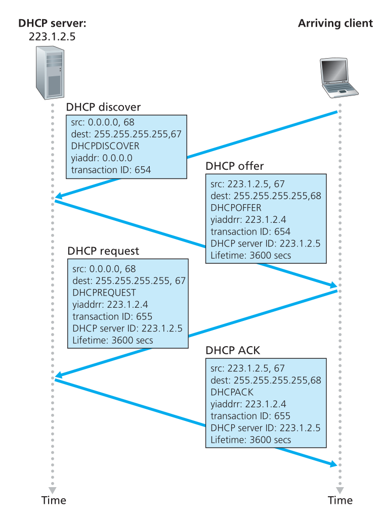
Figure 15: DHCP client-server interaction
NAT
To address allocation of IP addresses in small networks, the network translation protocol (NAT) has foundn increasingly widespread use. There are address spaces reserved for private networks, or a realm of private addresses. These are:
- 10.0.0.0/8
- 172.16.0.0/12
- 192.168.0.0/16
These addresses can be used without coordination with IANA or an Internet registry. These IP addresses only have meaning within the private network.
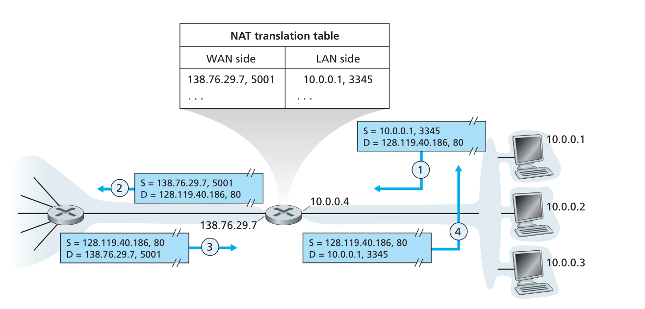
Figure 16: Network Address Translation
Routing
Recall that the Internet is a “network-of-networks”: A hierarchy of Autonomous Systems (AS), e.g. ISPs each own routers and links. Due to the size and decentralized administration of the internet, routing on the Internet is done hierarchically.
There are 2 forms of routing:
- Intra-AS routing
- intra-as routing finds a good patht between two routers within an AS. The 2 commonly used protocols are RIP and OSPF.
- Inter-AS routing
- inter-as routing handles the interfaces between ASs. The de facto protocol for this is BGP.
In intra-AS routing, there is a single administrator, so no policy decisions are needed. The routing policies here have a large focus on performance.
In inter-AS routing, admins will often want control over how traffic is routed, or who routes through its net. In this situation, policy may be prioritized over performance.
Routing can be viewed as a least-cost path problem between two vertices (routers) in a graph (network of routers).
Routing algorithms are classified as follows:
Link state algorithms. In this scenario, all routers have complete knowledge of the network topology, and the link costs. Routers periodically broadcast link costs to each other. Djikstra’s algorithm is often used to compute the least-cost path locally.
Distance vector algorithms. In this scenario, routers know physically connected neighbours, and link costs to neighbours. Routers exchange “local views” and update their own “local views”. An iterative process of computation is taken:
- Swap local view with direct neighbours.
- Update own’s local view.
- Repeat 1-2 until no more change to local view.
The Bellman-Ford equation is used to find the least-cost path:
\begin{equation} d_x(y) = \textrm{min}_v(c(x,v) + d_v(y)) \end{equation}
To find the least cost path, \(x\) needs to know the cost from each of its direct neighbour to \(y\). Each neighbour \(v\) sends its distance vector \((y, k)\) to \(x\), telling \(x\) that the cost from \(v\) to \(y\) is \(k\).
In the Distance Vector algorithm, every router sends its distance vectors to its directly connected neighbours. When router $x4 finds out that $y4 is advertising a path to \(z\) than \(x\) currently knows:
- \(x\) will update its distance vector to \(z\) accordingly
- \(x\) will note down that all packets for \(z\) should be sent to \(y\). This information will be used to create the forwarding table of \(x\).
After every router has exchanged several rounds of updates, every router would be aware of the least-cost paths.
the Routing Information Protocol (RIP) implements the distance vector algorithm. It uses hop count as the cost metric (insensitive to network congestion). In RIP, entries in the routing table are aggregated subnet masks (routing to destination subnet). Routing tables are exchanged every 30 seconds over UDP port 520.